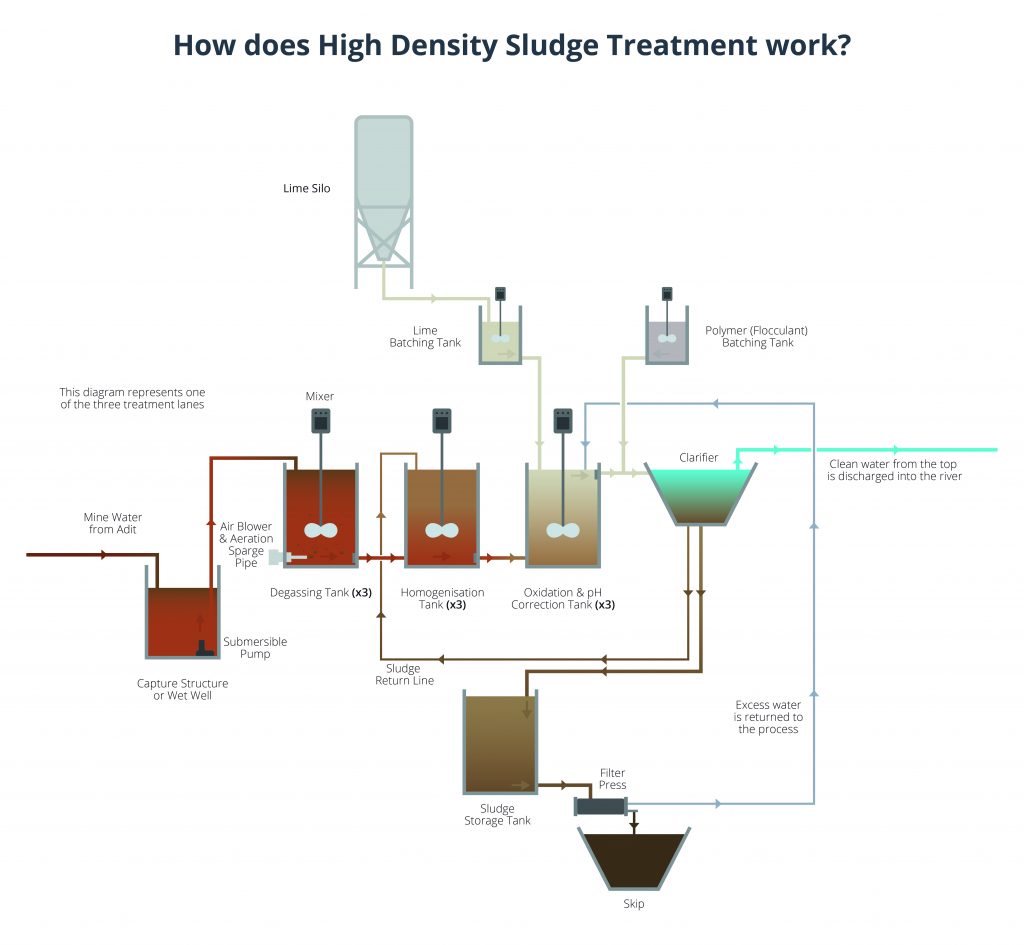
How does a High Density Sludge Scheme work?
Stage one: Capturing the mine water
A capture structure, similar to a small reservoir, will be built underground, next to the existing adit to capture the water escaping from the mine workings and divert it into the new treatment plant.
Submersed pumps in the base of capture structure will pump the water via a short length of pipework and the flow will be split and directed into the treatment lanes. The new treatment plant will have three lanes to treat the mine water and allow for planned maintenance.
Each lane is configured exactly the same and each lane will have a capacity of 100l/s. Each lane of mine water will flow into a degassing tank equipped with a mixer to agitate the contents.
Stage Two: Degassing & Aeration
The next stage of treatment within the treatment plant will be a de-gassing tank. The mine water, delivered by the pumps in the capture structure, will flow by gravity into the tank which is equipped with a mixer to agitate the contents.
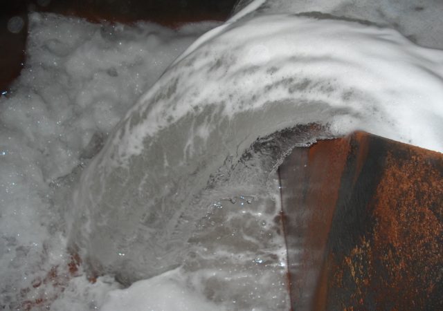
Air will be blown into the bottom of each tank, As the tiny air bubbles rise they will combine with the dissolved carbon within the mine water to form carbon dioxide which will naturally be dispersed (see diagram, below) to remove the gas. This will minimise the amount of lime required further down the treatment process.
Stage Three: Homogenisation
The mine water then flows into the Homogenisation Tank where a mixer makes sure the contents are uniformly mixed. This allows the pH to gradually increase and draw out the iron in the solution into tiny particles.
Stage Four: Oxidisation & PH Correction
The contents then flow into an Oxidisation Tank where lime is added from the Lime Silo. Lime reduces the acidity of a substance and is being used frequently in environmental protection work to comply with water quality regulation. By adding lime here, the pH will further increase.
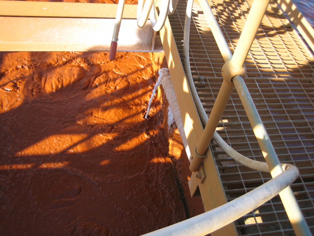
Lime dosing in action at our Wheal Jane site in Cornwall
Stage Five: Polymer Batching & Clarifier
Water is then dosed with polymer from the Polymer (Flocculant) Batching Tank. The polymer acts as a magnet to attract the suspended smaller particles of iron into larger groups.
The water then enters a Lamella Clarifier where the iron ‘sludge’ is allowed to settle to the bottom of the tank. Small portions of the sludge will be sent to the return line to be re-processed to pull out any further treatable water.
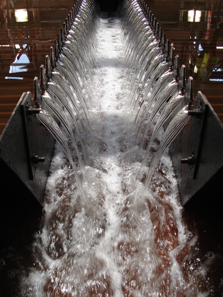
Clarifier tank at our Dawdon site
Stage Six: Discharge
Water will overflow from the top of the clarifier as treated water and discharged back to the River South Esk. The settled sludge in the bottom of the clarifier will be sent to a filter press via a sludge storage tank for any excess water to be pressed out.
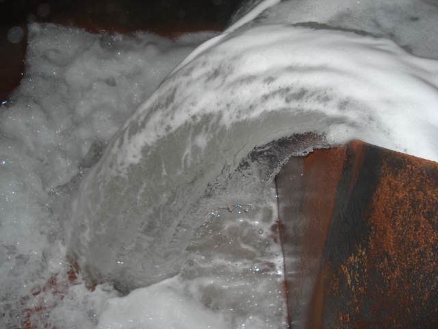
Treated water being discharged at Dawdon
The dried sludge will be sent to a skip to be removed from site whilst the pressed water is recirculated for treatment.
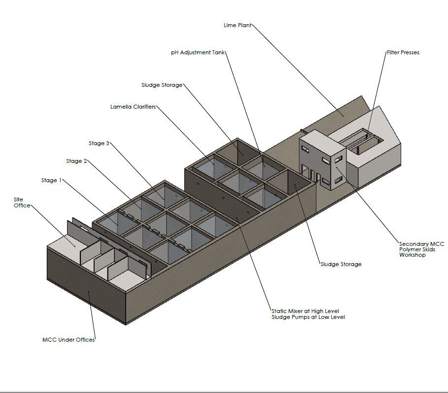
Below is a diagram illustrating the overall process rendered by our digital team.
